Ah 4 Control Cable
My current antenna is the B.A.L. -- a large, horizontal loop that's about 150 meters of wire about 15-20 meters up in the trees around the yard. I think it's a great all band antenna.
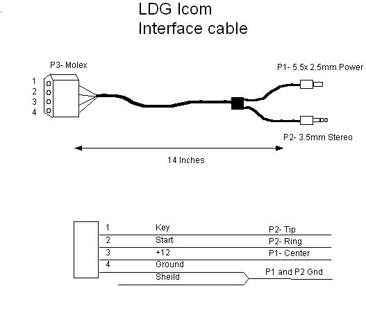
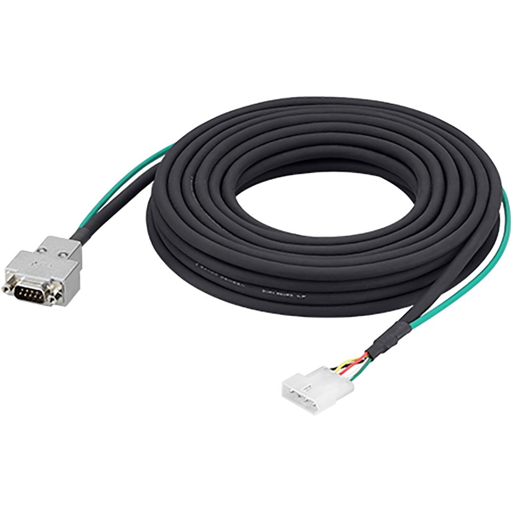
This is the green wire on the AH-4 cable. Pin 2 is the START pin to/from the microprocessor. Under normal circumstances the START pin is pulled high when a remote tuner is attached to tell the radio that the tuner is present. When you press 'TUNE' the radio pulls the pin low telling the tuner to start the matching sequence. Build a control cable for the AH-4. Build a conversion cable that is connected to the AH-4 supplied cable. When you chose No.1: Purchase a 4-conductor shielded cable and build the control cable. One side is for the J2 connector in the AH-4, the other side is for the IC-705 TUNER jack and the DC power supply. The 4-conductor shielded cable.
I buried a couple of coax runs from the shack wall to a spot about 15m away behind a large bush. The ladder line from the loop falls down to this spot so I do not have wires directly hanging off the house (which makes the YL happy). I was using a DX Engineering MAXI-CORE Balun and was happy with the results. (As an aside: I love hamfests! I picked up this used balun for a song.
 ) I used this setup for a few years and have been pretty happy with the results.
 Since the loop is a non-resonant antenna, the SWR can be high. I've been using the tuners built into my transceivers (Elecraft K2 & K3) but have been concerned about loss in the coax. Since I only run 100 watts or less, I want every bit of power to get to the antenna and not be used to heat the coax. Placing a tuner at the end of the coax run is supposed to reduce the coax loss. I had always planned on adding a remote tuner when the budget allowed. When I buried the coax, I also threw in a couple of runs of CAT-5 cable that I had laying around for use for some sort of remote control.
| The remote connection at the end of the coax run |
| All connected and ready to go! |
| The 'controller' in the shack |

 I've been very happy with the tuner so far. It finds a decent match (less then 1.5:1) on all bands and I believe it has made a difference. I don't have empirical evidence to support that, though! At least I no longer worry about loss in the coax...
Technical Segment
Using the Icom AH-4 with the IC-705
In this article, FB NEWS Worldwide editors are going to introduce how to use the Icom AH-4 Automatic Antenna Tuner with the IC-705. It is reported that an Icom antenna tuner especially for the IC-705 is being planned for release, but we just wanted to use a wire antenna with the IC-705 “right now.”
Please note that this is not an officially recommended method by Icom.
Ah-4 Control Cable
Pin assignments of the IC-705 TUNER jack
Shielded Control Cable
There is a TUNER jack on the right side of the IC-705, and according to the Icom webpage, an antenna tuner will be released in the future that can be connected to it.

Right side of the IC-705
This is a three-conductor stereo jack, and [KEY], [START], and [GND] are assigned sequentially from the tip.

Pin assignment
Connecting the AH-4 to the IC-705
Unlike the IC-7610 or IC-7300, there is no jack especially for the AH-4 on the IC-705. However, we assumed that if we connect the control lines of the AH-4 to the IC-705’s TUNER jack, and separately supply the 13.8 V DC power...the antenna tuner might work well.
When the AH-4 is connected to the IC-7300, the 13.8 V power is supplied from the radio to the AH-4.
When the AH-4 is connected to the IC-705, both the AH-4 and IC-705 must be connected to the same power supply and grounded at the same internal GND terminal.
To connect the AH-4 to the IC-705, connect the three control lines for KEY, START and GND to the tip, ring, and sleeve of a 3.5 mm stereo plug. Connect the fourth power line to a suitable power connector, which is required to supply 13.8 V DC power to the tuner. You can purchase a 3.5 mm stereo plug at a parts shop, but we also recommend trying out a screw-type connector.
Direct wiring with a screw-type connector is convenient for a trial.
Now, there are two ways to connect the AH-4 to the IC-705.
1. Build a control cable for the AH-4.
2. Build a conversion cable that is connected to the AH-4 supplied cable.
When you chose No.1:
Purchase a 4-conductor shielded cable and build the control cable. One side is for the J2 connector in the AH-4, the other side is for the IC-705 TUNER jack and the DC power supply.
The 4-conductor shielded cable we bought.
When you chose No.2:
To make a conversion cable, buy the necessary spare parts described below. Contact your local distributor for ordering details. Because the AH-4 standard supplied cable is too long for the IC-705, you can cut and shorten it if needed, but we are not responsible for any trouble that may occur.
Required spare parts:
...female, radio side
Component name: 1490R1
Icom component number: 6510001940
...4 pins are required
Component name: 1189TL
Icom component number: 6510007460
Completed conversion cable
Verifying operation
This is a screen capture before we connect the AH-4 to the IC-705. [TUNER] is grayed out.
The IC-705 FUNCTION screen before connecting
Connect both the AH-4 and the IC-705 to the same regulated power supply after turning it OFF. Then turn ON the power supply to power ON the AH-4 first, then push the [POWER] key in the IC-705 to turn ON the IC-705. This sequence is important for the AH-4 to be recognized by the IC-705. Now look at the IC-705 FUNCTION screen again to confirm that [TUNER] is no longer grayed out. Touch and hold [TUNER] for one second to turn it ON.
The IC-705 FUNCTION screen after connected
When tuning is started, the [TUNE] icon blinks red in the upper-left corner of the IC-705 screen. When tuning is complete, the icon stops blinking and is lit white.
The IC-705 screen after tuning
We look forward to seeing the Icom antenna tuner!
Icom Ah-4 Control Cable
Now we figured out that we can use the AH-4 connected to the IC-705...but we can’t wait for the official Icom antenna tuner, to bring out the best in the IC-705!